The series so far:
- Translating a SQL Server Schema into a Cassandra Table: Part I Problem Space and Cassandra Primary Key
- Translating a SQL Server Schema into a Cassandra Table: Part II Integrity Constraints
- Translating a SQL Server Schema into a Cassandra Table: Part III Many-to-Many, Attribute Closure and Solution Space
Integrity constraints, including functional dependencies, guide the modeling process for relational database systems. They are no less important when designing Cassandra structures – although support can be limited.
This second of the series revolves around four separate problems to solve, each presenting modeling principles in Cassandra and some in SQL Server as well. Each highlights different facets. In the first, tracking surgeries in an OLTP relational model is straightforward, but there are alternatives in Cassandra.
In the second, complex integrity constraints for plane rentals are covered in several ways in SQL Server but prove problematic in Cassandra. The third problem presents a series of unrelated functional dependencies from which I deduce rules for Cassandra key design.
The last to solve then breaks the rules with architects and blueprints to reuse a Cassandra base table as the basis for other tables.
Each example is meant to be an enjoyable logic puzzle in itself. You need a background in Cassandra key and table design as gotten from Part I or elsewhere as well as experience with relational systems.
Collections and Key Uniqueness
Consider the following entity-relationship diagram (ERD):
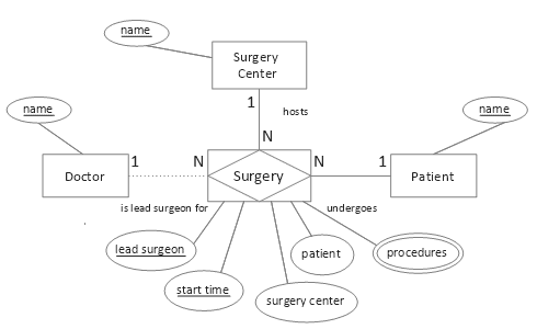
Figure 1. Conceptual surgeries model
In a normalized relational physical model, the multivalued procedures attribute would comprise its own table, its composite key containing a foreign key referencing the associative table (from the associative entity) for Surgery and using appropriate cascading referential integrity to prevent orphans. The associative table, in turn, could have three unique constraints: the primary key as shown, plus (Patient, Start Date Time), and (Surgery ID). This is straightforward.
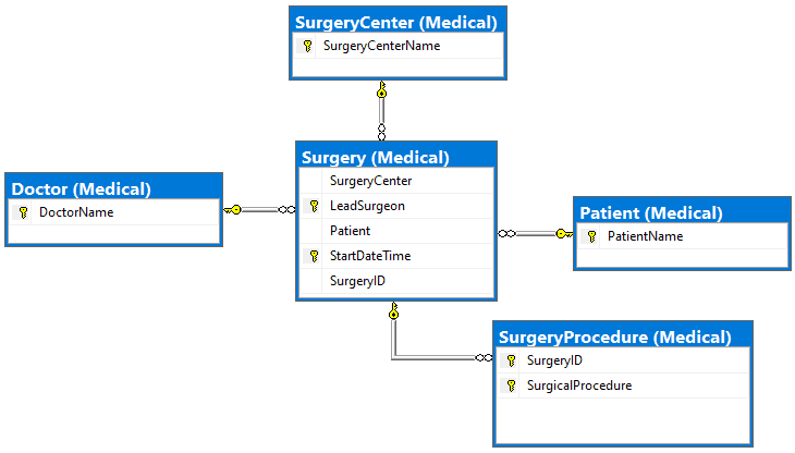
Figure 2. SQL Server physical solution
In designing a Cassandra table, though, often there are more choices. Assume this access pattern:
Qk. Find lead surgeons and procedures performed at a surgery center for a given week
Here is one possible design (all code examples can be found here):
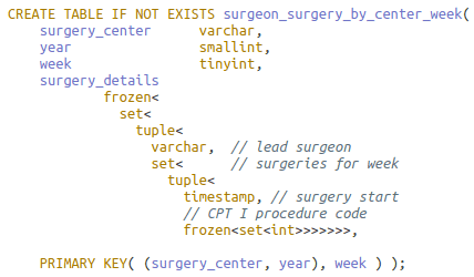
Numeric columns year and week together identify the week (see readout below). Column year as a partition key prevents the partition from growing unbounded.
All told, by inserting nested collection type surgery details, the design is apropos for the query, and the primary key meets the uniqueness criteria. The problems are, however, the complexity and size of surgery details.
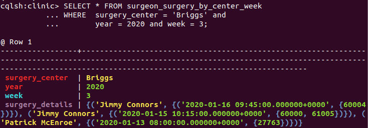
The DataStax CQL shell (cqlsh) displays query result partition columns in red, clustering columns in aqua, regular (non-key) columns in mauve and statics in white.
There is not a way in CQL to retrieve a smaller segment of the potentially substantial surgery details column, e.g. by surgeon or date. Solely by removing the lead surgeon from the nested collection and appending it to the clustering column list, though, the collection’s size and complexity shrinks; its number of collections reduces from five to three:
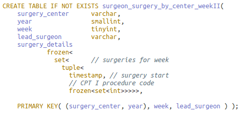
This key is also unique! Because of collections, the infamous 1NF violator, there is no danger of compromising Cassandra data by making keys out of non-minimal superkeys as happens in poor relational designs.
Notice that the same query can be reused on this revised table. One more row is returned, each with less (inapplicable) data:
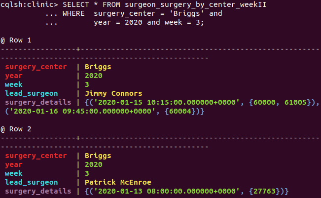
A query now has the flexibility to restrict on the lead surgeon as well if known via the application’s workflow. Further, an aggregate query can count the distinct doctors performing surgery in the week.
The process can be extended. Surgery start time could also be taken from surgery details and appended after lead surgeon in the key, leaving surgery details as a single set of procedure codes. Similarly, the codes could be appended and surgery details removed. Each clustering column addition places the rowset at a finer granularity, i.e. more rows albeit with less, but more focused, information.
Another option affecting the number of rows in a partition is to slide keys in or out of the partition.
In this exercise, placement and suggested possible placement of key attributes all follow the correct ordering of attributes. This concept will be explored in section Placement of Functional Dependencies below.
Enforcing Integrity Constraints
Say a proof-of-concept Cassandra database monitors a single flight club under the auspices of the Federal Aviation Administration (FAA). A transactional plane rental table to be designed is bound by these integrity constraints (IC; aka enterprise/business rules):
- A member can rent at most one plane on any day
- A plane can be rented at most once on any day
- Rentals require a single credit card payment
- A set of credit cards uniquely identifies a member
- Violation of club or FAA or other rules disqualifies a member from renting a plane
In a relational system, point 5 requires procedural code to enforce. Functional dependencies (FD), a special class of IC, can be deduced from points 1 through 4. Here they are using letter abbreviations M: member, D: day, P: plane, C: credit card, and ‘→’ for functionally determines:
- DM → P IC 1.
- DP → M IC 2.
- C → M IC 4.
- DM → C IC 1. and 3.
Together these FDs imply three overlapping candidate keys. This can be proven using Armstrong’s Axioms and secondary rules. I’ll show one – DC as candidate key – and omit the rest.
- DC → DM (3, augmentation)
- DC → P (1 and 5, transitivity)
- DC → DMP (5 and 6, union)
- DC → DCMP (7, augmentation)
The candidate keys can be displayed graphically, the bold R as shorthand for all columns in the relation:

Figure 3. Two functional dependency diagrams for the Plane Rental table
The diagrams imply an interesting barebones relational table: there are no non-prime attributes. A non-prime attribute doesn’t appear in any candidate key. Further, owing to functional dependency C → M, the table would be in 3NF, with redundancy occurring with each repeated credit card-member pair.
This sketch is enough to start modeling. I’ll defer for the moment the design considerations in Cassandra and continue with a sample physical model of the transactional table in SQL Server:
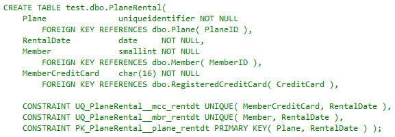
As expected, foreign keys reference tables with more related attributes. Unique constraints represent the three candidate keys, the Plane-Rental Date pair having been elevated to the primary key. This satisfies ICs 1 and 2 and the implied IC involving 3. Member credit card as non-null implies the credit card payment in point 3. What remains is addressing integrity constraints 4 and 5.

The code snippet is taken from an insert-update trigger on the table to enforce point 4, the rule that credit cards functionally determine members. (This can also serve as a rudimentary basis for a fraud detection system (members as drug smugglers, e.g.)). A more advanced prototype trigger would include joining on the registered credit card table (not shown).
This next snippet is from a second insert-update trigger that joins another table to satisfy rule 5, ensuring a member is cleared to fly:
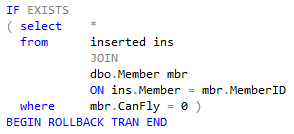
The relational table Plane Rental in its very definition covers every integrity constraint required of it. Now switch the effort to Cassandra.
This is the data access pattern for which the table – the precomputed, sorted result set – is to be modeled:
Qn. Find member rentals for a given plane.
The phrase “for a given plane” signals that attribute plane should be in the partition key. The choices for the full primary key, then, are these: ((P)) or ((PD)) or ((P)D), the inner parentheses separating partition keys from clustering keys. The first choice ((P)), a deviant (unique) key, creates a single row for each plane with a possibly large collection, unsuitable for a transactional workload. This situation was discussed in the previous section.
The second ((PD)) addresses the access pattern but is non-performant as Qn. queries may access many nodes over the cluster.
That leaves ((P)D).
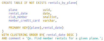
The table definition allows for one manageable row for each plane-day pair on one partition. Below is a sampling of data legal for the table:

The result is failure on all but one integrity constraint. Restricting a plane rental to at most once in a day, FD point 2 (DP → M), is satisfied by the primary key. Point 1, though, limiting a member to at most one rental a day {DM → P}, is shown violated by rows two and four; Cassandra doesn’t support alternate keys (think of the complexity and expense in a distributed data system).
Requiring credit card payment, point 3, fails in the first row; in the Cassandra wide-row model, any regular value may be missing from a row, displayed here as null. Point 4, in which a set of credit cards uniquely identifies a member (C → M), is not enforced, as seen in rows two and three. Recall that it was verified in the SQL Server trigger.
The readout does not indicate if point 5, which disqualifies a member in violation of rules from renting a plane, is being enforced – another trigger-based test not available in Cassandra.
Integrity constraints don’t go away when the storage/retrieval engine changes. Most enforcement in Cassandra must be written in the client app(s). Bulletproofing that was almost paint-by-the-numbers simple now requires more effort.
Placement of Functional Dependencies
As seen in the previous section, functional dependencies are an important type of integrity constraint. For this section, consider these attribute sets and their many-to-one (‘→’ ) relationships in the unified relation:
![]()
Figure 4. Unrelated functional dependencies
In Part I, I introduced the unified relation as a container for entities, attributes and relationships of interest to an access pattern in the logical design phase. Besides placing focus on relationships to support, much Cassandra analysis relies on functional dependencies, which exist only in relations.
Attribute sets in a functional dependency relationship can appear anywhere in the primary key or as regular attributes or spanning both. This diagram shows placement – poor placement, to be discussed – using Cassandra conceptual row nesting disc layout:

Figure 5. Functional dependency errors in partition and clustering keys
The first problem occurs with the partition keys. CQL queries in support of an access pattern mostly restrain on all partition attributes. It may make sense for the access pattern to place the A attribute set in the partition, or the B set. Importantly, however, it makes no sense to place them both in the partition. Doing so cannot affect logical partitioning and can only complicate querying. One is in, and one is made static, assuming there are clustering keys.
(Recall that a static column’s value is stored once per partition, not once per row. Making a column static only makes sense when it is in a relationship with a subset of the partition columns and clustering columns exist. Depending on the relationship type (not necessarily functional), a static may store an atomic value or be a collection type or user-defined type (UDT).)
The second problem occurs with clustering keys C and D. In the diagram, the dependent D follows the determinant C. As a result, many C values converge on a single D value. This buys nothing. Rather, the D dependent side cannot affect searching, sorting or uniqueness, and can only complicate queries.
Now imagine the D dependent occurring before the C determinant. The search space now correctly expands in the conceptual row nesting. If C is holes and D is a golf course, each course correctly diverges into many holes.
These two issues suggest a pair of general rules for primary key design given non-overlapping attribute sets X and Y such that X → Y. X must be irreducible (no attribute can be removed or the dependency is invalidated) and all attributes of X are in the key. For Y, take it to mean any non-empty subset of Y appearing in the key:
- X and Y can never appear together in the partition
- Regardless of where X and Y appear in the primary key, dependent Y must precede determinant X
In clarification of the second point: only (a subset of) Y may (or may not) be in the partition, as per the first point.
I illustrate both rules with an example.
Say the table is to be built for this access pattern:
Qn. Find product lines by industry and manufacturer
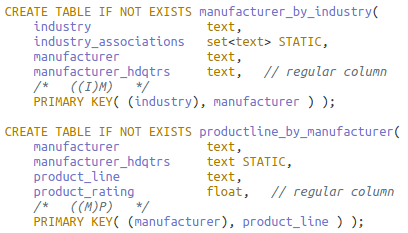
Identifiers for product line (P), industry (I) and manufacturer (M) are in a hierarchical FD relationship such that P → M → I as in Figure 4. Here is the initial physical table developed from the logical model (not shown); it follows both rules:

The advantages are single-pass querying over one partition and redundancy limited to the manufacturer columns. If ‘I’ and ‘M’ together would not be available through all relevant, connected application workflow paths, however, Qn. and the table may need to be rethought, or the deficient workflow paths/access patterns amended. For the exercise, assume the former tactic – but consider how the solution next still alters the workflow path.
The table is split in two. The first table is made by sliding over the ‘M’ to make it a partitioning key: ((IM)P). By the first rule, this reduces to ((M)P) with ‘I’ as static (if needed). It also remains in agreement with the second (and eliminates redundancy on manufacturer columns).
Could another access pattern require its reverse, ((P)M)? This would falsely imply that a product line can be made by multiple manufacturers, in violation of the integrity constraint formalized as P → M (and the second rule). Instead, a single-row partition ((P)) may hold all product line details for access later in the workflow.
I think you can deduce the second table: ((I)M), also in accord with the rules. Here they are:
There is, though, a significant exception to these rules. See the next section.
Materialized Views
In the problem for this section, tables for queries on custom homes need to be designed. Here are the integrity constraints:
- Each blueprint is attributed to one architect
- An architect develops one or more blueprints
- A blueprint is registered before the house is built
- A blueprint cannot be reused
This entity-occurrence diagram captures the integrity constraints:
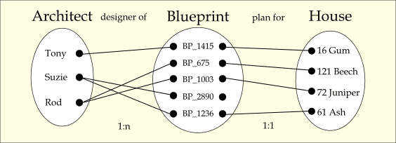
Figure 6. Merged occurrence diagrams
The architect-blueprint “designer of” relationship is one-to-many (1:n) with total participation, and the blueprint-house “plan for” relationship is one-to-one (1:1) with blueprint having partial participation.
There are several access patterns needing tables that reference the three entities and their attributes. Unlike in preceding designs, though, the tables can be defined on a single base table and automatically managed and updated by Cassandra as the base table changes.
This is the access pattern for the base table:
Qi. Find blueprints and houses for a given architect.
Below is the sample table definition:

Acronym NCARB means National Council of Architectural Registration Boards.
The base table purposely and necessarily follows the two rules from the previous section and has all the data – there is no loss of information:

It is also a rare table in that there is no redundancy. (Don’t let the readout fool you: although static is ncarb certified appears in every row in the readout, it is stored once per architect (partition)).
The first materialized view table is defined for this access pattern:
Qi. Find architect and blueprint information for a given house address.

The base table is referenced in the FROM clause. In the WHERE clause, each primary key column is restricted at minimum to be non-null for key correctness.
Notice that static column is ncarb certified is not in the SELECT list. There is now some information loss as static columns cannot be included in materialized view definitions:

More critically, now the rule placing determinants after dependents is violated. House address, elevated from regular column to partition key, functionally determines both clustering keys architect and blueprint. This may happen in the view. All primary key columns in the base must be, in any order, in the view primary key to preserve the 1:1 mapping from base rows to a subset of rows in the view. Failure to do so could collapse multiple rows into one from base to view and is prohibited.
This is a second access pattern:
Qk. Find all houses constructed for an architect.
This mirrors the previous view except that the house address moves from the partition to the end of the clustering key list. In restricting the address to non-null, not all of Suzie’s base table rows are in the view as the readout following the definition shows:


This is the final access pattern:
Ql. Find architect and house design information by blueprint.
To realize the view, simply reverse the partition and clustering keys from the base. In contrast to the previous view, house address is not in the key lest it incorrectly remove rows given blueprint’s partial participation with it.


As with the base table, the view table has no redundancy as any attributes in a cardinality relationship with the architect should be static, and statics aren’t carried into the view.
Conclusion
You saw that integrity constraints and functional dependencies are just as crucial for Cassandra design and, although only implied, table updates and maintenance as well.
On the relational side, built-in features and theory are tremendous aids in modeling. For the surgery problem, the way was clear in translating entities and a multivalued attribute into interconnected tables and using cascading referential integrity appropriately. For the plane rental problem, it was translating some ICs into FDs, and reasoning from them to apply a mixed strategy of unique and referential constraints and triggers to cover all ICs.
In Cassandra, the first lesson was about moving non-key attributes to the key and enlisting (nested) collections to ensure the key is always unique. In the next, you saw how, having only a primary key for IC enforcement, a legal instance of a Cassandra table can violate almost all ICs.
The third presented two rules for placement of FDs in the primary key: disallowing determinants and dependents both to reside in the partition and ordering of dependents before determinants to ensure proper nested row layout.
Finally, the discussion on materialized views showed that the base table must follow the rules, but the views built on the base necessarily don’t. Materialized views enable reusing of data with automatic synchronization.
Last Word
Imagine building a SQL Server backend for a medium- to large-size OLTP application. You enforce a clean separation of concerns between app and database, allowing only execute permission on stored procedures in a handful of schemas. Whether you agree with me that this is a best practice – a topic for another day – one thing is clear: coupling between the two is as loose as can be.
All I’ve discussed points to the fact that, in contrast, Cassandra and OLTP apps are as tightly coupled as possible. Do you want integrity constraint enforcement? Mostly, write it in the app.
Looking ahead, the last article in the series is in three parts. The first discusses the common case of many-to-many relationships in the ERD. The second presents a function for doing attribute closure given a set of functional dependencies. This process has important implications for key and table design and functional dependency enforcement.
The last part returns to the original problem; solutions, given all the background, now come easily.


Load comments